In short, the new project centers around a TENG-covered glove that detects the bending moments and contact separation between fingers and phalange skins. C-TPU, which would be used here as the electrode layer again, showed some interesting properties when put under different types of strain in past studies. Specifically, under tensile stress, the resistance decreases — albeit in a parabolic route that results in the final resistance being lower than before — and after around 250 cycles of strain-and-release, the parabolic change in resistance becomes predictable (Riddervold et al., 2024).
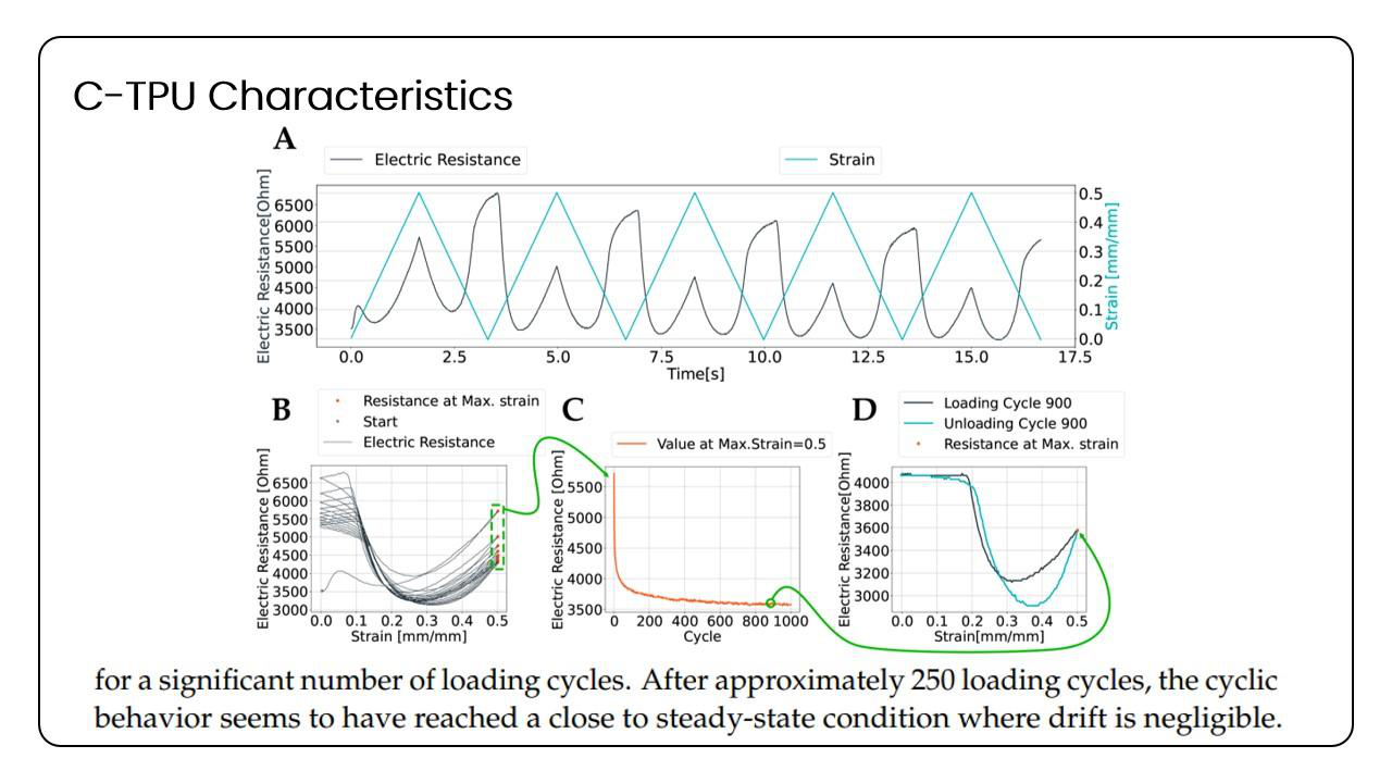
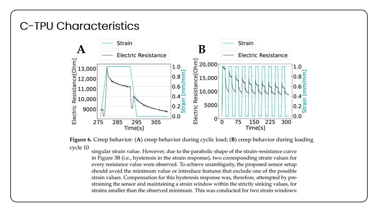 Slides created by Gihyun Kim, figures taken from Riddervold et al., 2024
Furthermore, when the stress is held for a certain period of time, the material exhibits a creep behavior where the resistance decreases as the C-TPU is under such stress — a characteristic I believe would be useful for the glove's signal detection method (to be discussed later).
Although the authors did not specify why the overall resistance drops to a "steady state" after approximately 250 cycles of stress-and-release apart from hysteresis, I believe that it may be due to the repositioning and realignment of the carbon atoms within the C-TPU. Most commercial C-TPU filaments (such as the one used in the studies mentioned in this report) are made using a carbon black structure where spherical particles of carbon are fused into irregular patterns during manufacturing. As the strain and release is repeated, the carbon particles would constantly rearrange themselves and eventually reach the "steady state" where the alignment would perhaps best minimize the entropy of the system (causing the aforementioned hysteresis).
Overall, the change in resistance under tensile stress and the creep behavior shown when that stress is maintained could be used to detect the bending of the finger through specific attachments of the material.
On the other hand, under flexural stress, the resistance of the C-TPU appears to monotonically decrease in what the authors call a negative gauge factor (nGF) (Özkurt et al., 2026).
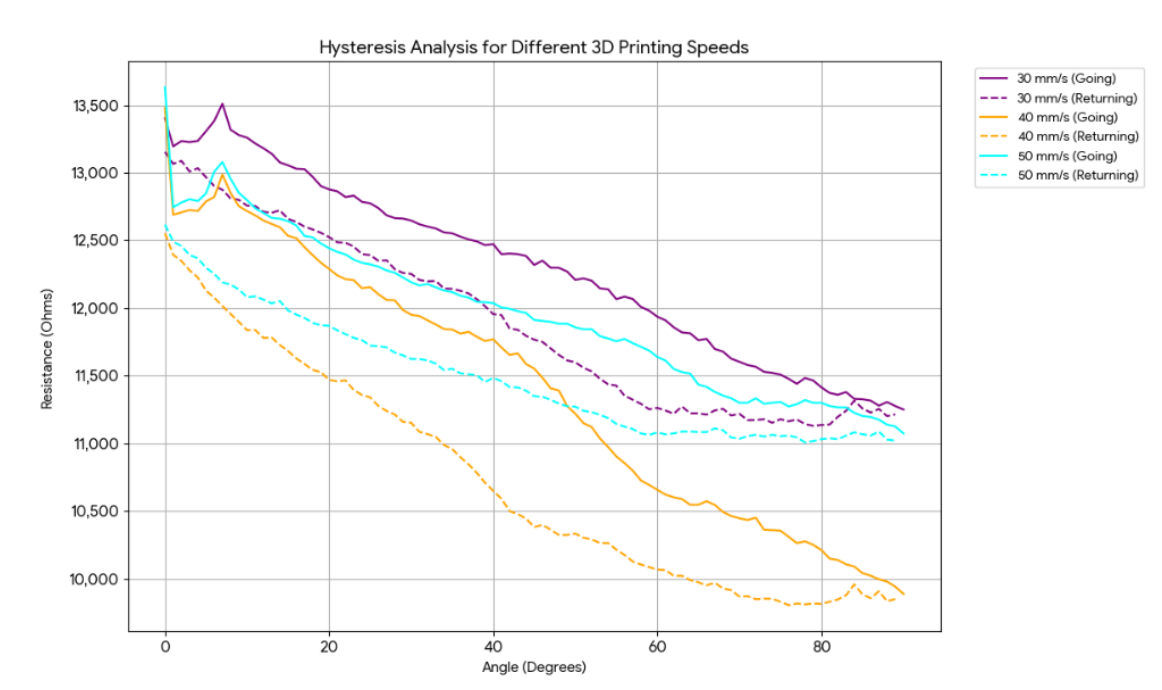 (Özkurt et al., 2026)
Using these properties of C-TPU and previous experiments with gyroid structures and TPU structures, the below idea was conjured.
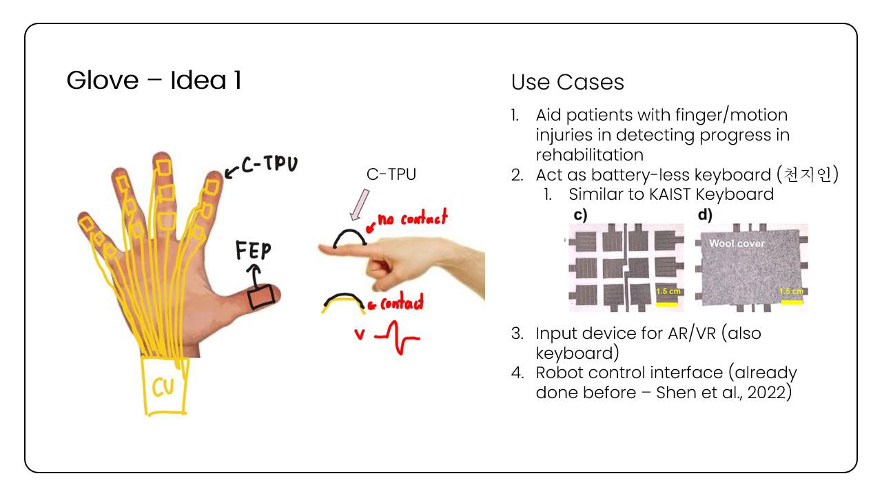
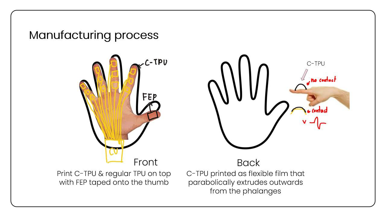 Slides and figures created by Gihyun Kim
On the front of the hand, the four fingers would have 4 × 4 mm C-TPU patches with the thumb being coated in FEP, which will detect signal via contact separation. On the back side, each finger will have parabolic extrusions of C-TPU that will use the aforementioned qualities to detect changes in resistance to measure changes in finger and hand motion.
Building the test rigs
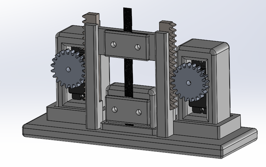
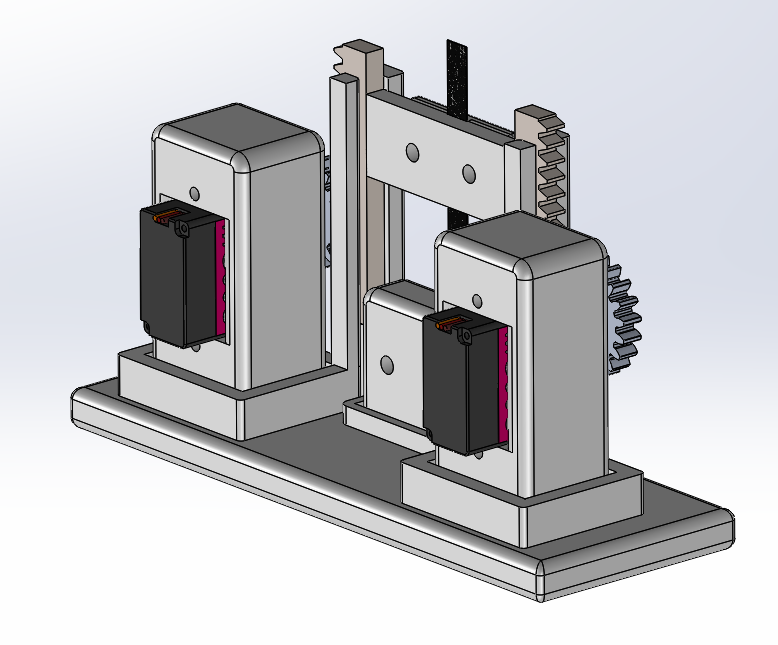
To test these traits myself, I designed a tensile and a bending test machine using SolidWorks, which are both being 3D printed using PETG at the time of writing. An Arduino Uno with voltage sensors will be used to detect the change in resistance values (if any).
Tensile tester
Bending tester
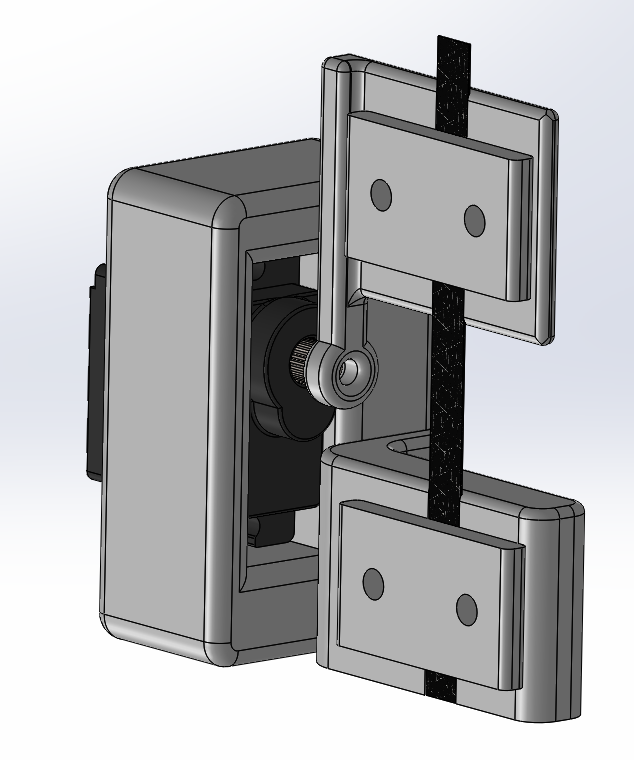
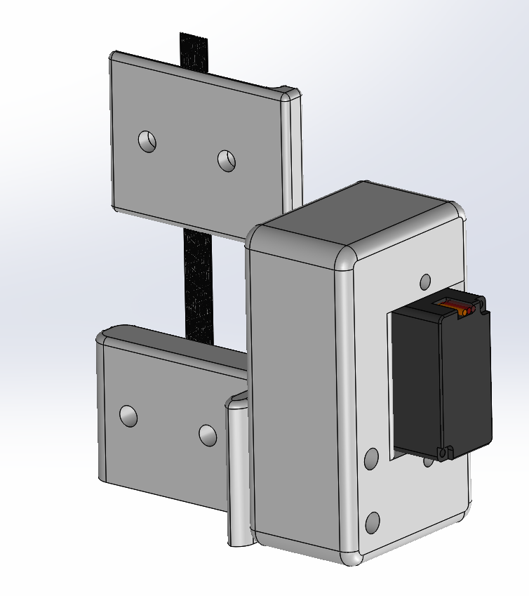
Download the models: Tensile Tester (STL) · Bending Tester (STL)
Results of the test will be posted in subsequent progress reports.
References
Özkurt, A., Gürkan Kuntalp, D., Kayacan, O., Kayacan, Ö., & Aral, S. N. (2026). Geometrically Optimized FDM-Printed Conductive TPU Bend Sensors for Hand Rehabilitation. Sensors, 26(8), 2309. https://doi.org/10.3390/s26082309
Riddervold, A., Nesheim, O. S., Eikevåg, S. W., & Steinert, M. (2024). Electrical Resistance Response to Strain in 3D-Printed Conductive Thermoplastic Polyurethane (TPU). Applied Sciences, 14(9), 3681. https://doi.org/10.3390/app14093681