The first step of creating the aforementioned structure in RA Progress Report — 1 was to first generate the TPU gyroid structure using a MATLAB script, then export it as a .stl file which would then be sent to the Prusa Slicer to be printed. This concept was previously proven where TPMS structures were 3D printed in similar fashion (Peng et al., 2022). Though the structures printed and further tested are drastically different, the concept of MATLAB-to-3D-printing remained viable for this study. Therefore, the following MATLAB script was created.
grid_size = 60;
inner_size = 30;
thickness_z = 1.0;
resolution = 300;
unit_cell_size = 3.75;
w = 2 * pi / unit_cell_size;

x = linspace(-grid_size/2, grid_size/2, resolution);
y = linspace(-grid_size/2, grid_size/2, resolution);
z = linspace(0, thickness_z, 30);
[X, Y, Z] = meshgrid(x, y, z);

U_Gyroid = sin(w.*X).*cos(w.*Y) + sin(w.*Y).*cos(w.*Z) + sin(w.*Z).*cos(w.*X);

dist_from_center = max(abs(X), abs(Y));

transition = 1 ./ (1 + exp(-1.5 * (dist_from_center - inner_size/2)));
threshold_map = -0.6 + (0.8 .* transition);

[f, v] = isosurface(X, Y, Z, U_Gyroid - threshold_map, 0);

if isempty(f)
error('Geometry too thin for current cell size. Reduce unit_cell_size.');
else
tr = triangulation(f, v);
stlwrite(tr, '3D_TENG_Fabric.stl');

% Visual Check
patch('Faces', f, 'Vertices', v, 'FaceColor', [0.4 0.4 0.4], 'EdgeColor', 'none');
daspect([1 1 1]); view(3); camlight; lighting gouraud;
fprintf('Saved: 3D_TENG_Fabric.stl with Z=%.1fmm\n', thickness_z);
end
The script utilizes the implicit gyroid equation of
sin(x)cos(y) + sin(y)cos(z) + sin(z)cos(x) = c
where x, y, z are the spatial coordinates and c is the isosurface constant (controls the porosity of the gyroid structure).
Using the script, the following structure was created:
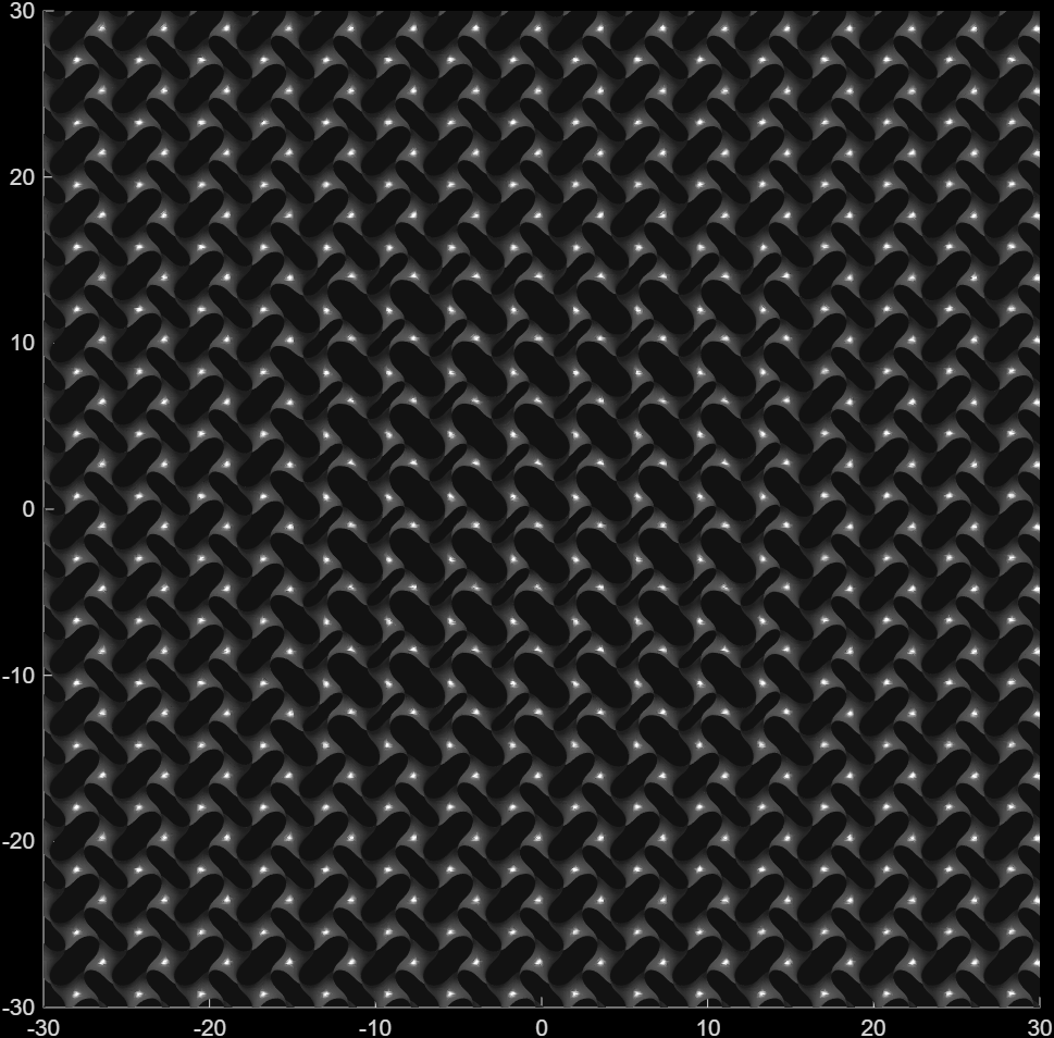
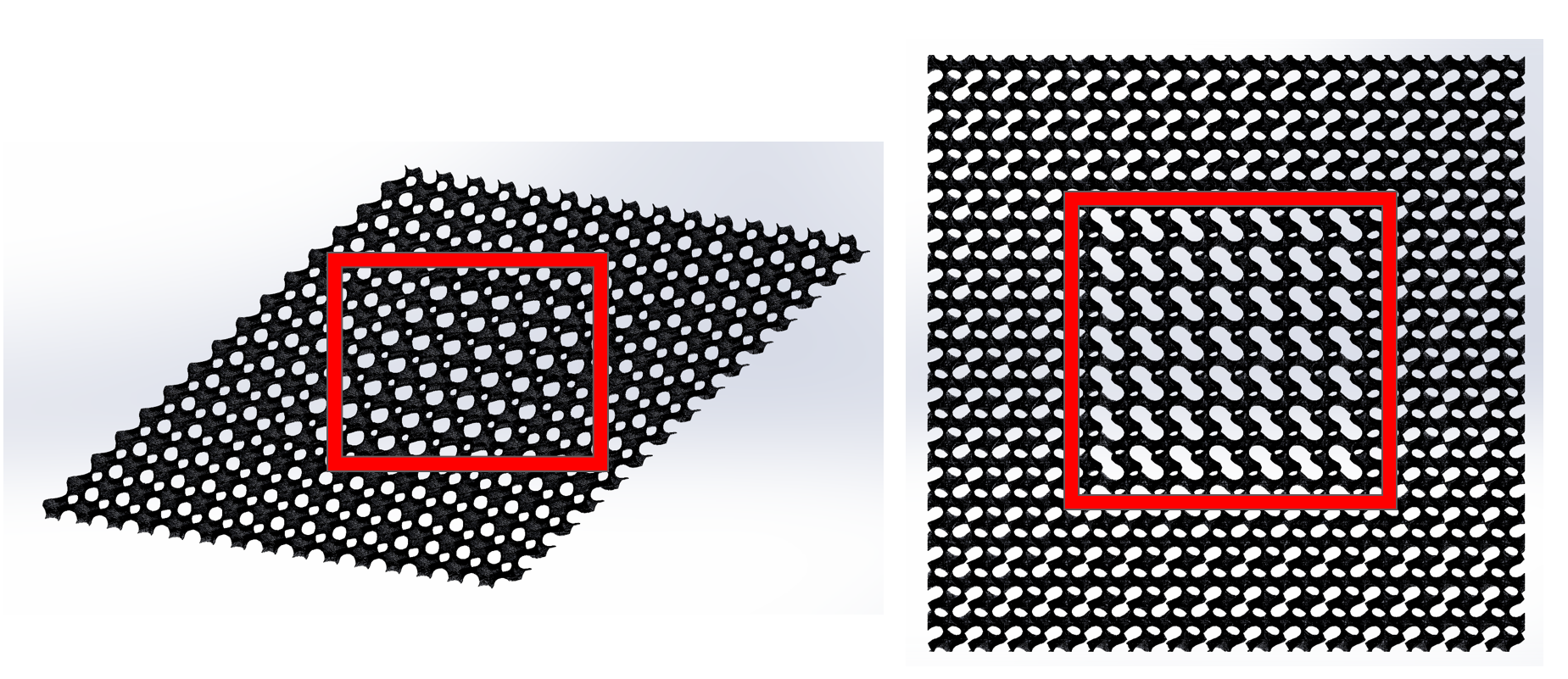 Section enclosed by the red box indicates the stress-resistant region where the electrodes would be placed.
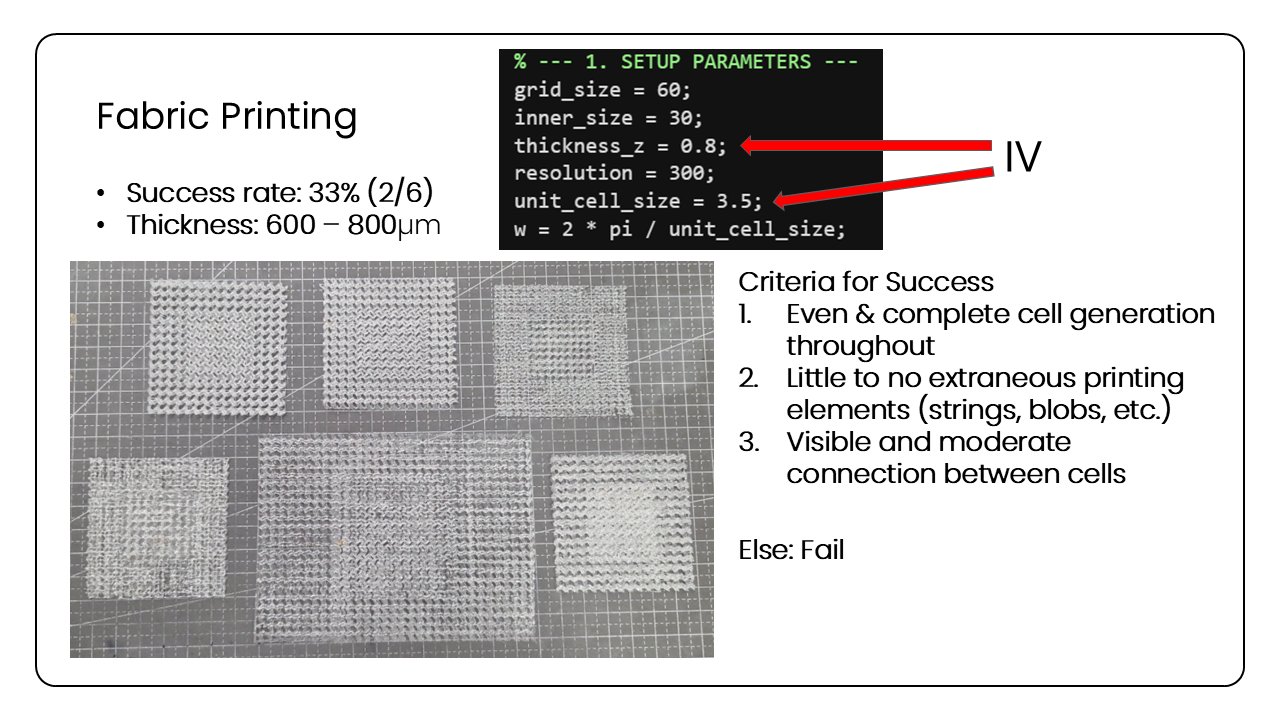
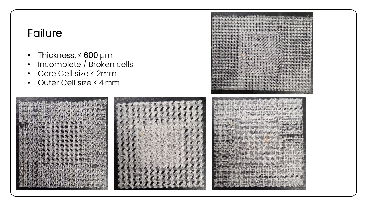
However, after weeks of attempting to realize this concept, which proved valid in concept, the 3D printing consistently failed, with the following images providing an analysis of the print results (these slides were presented to the SHIN Group members on 04/06/2026).
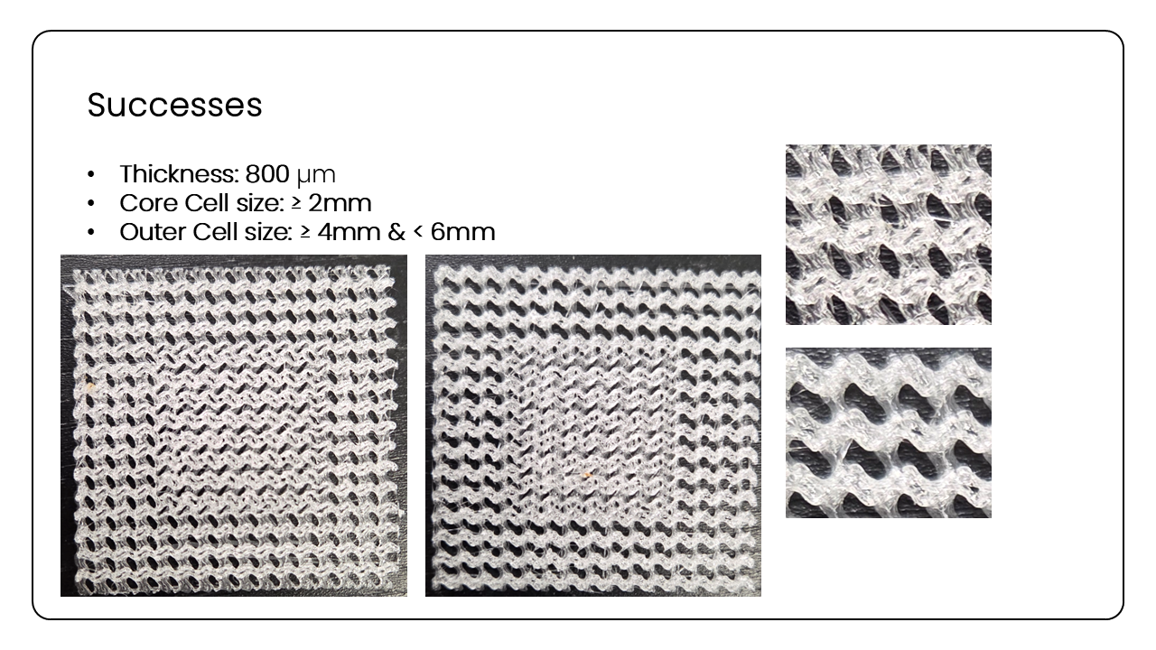
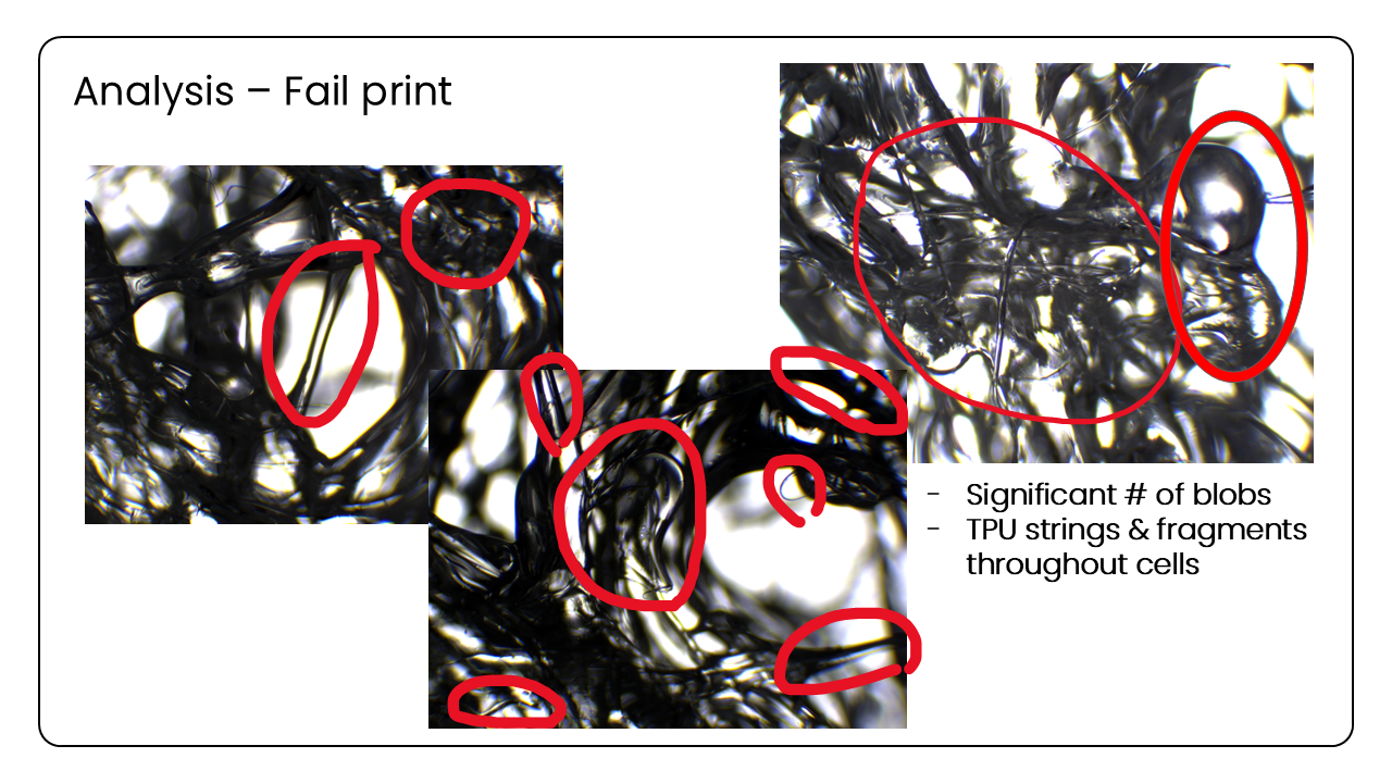
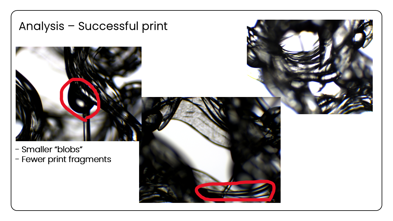
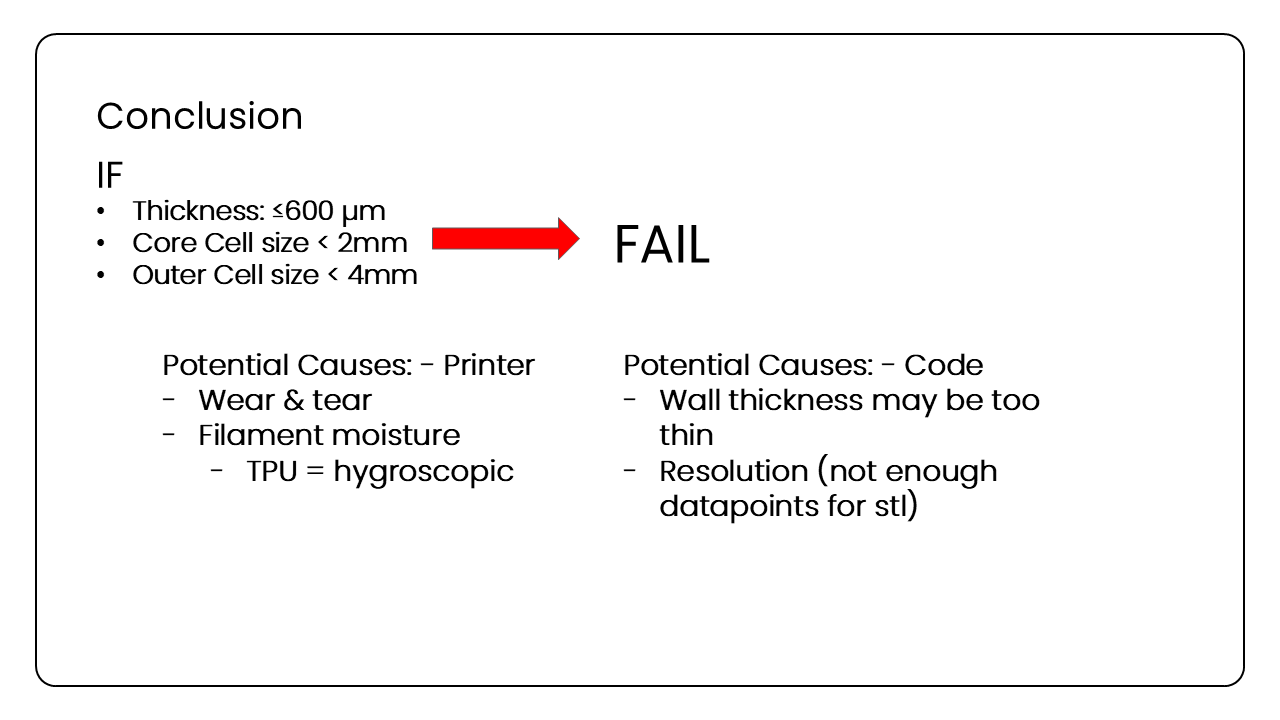
On the bright side, the electrode pattern testing did prove to be successful: a grid structure composed of Glass (substrate) – X electrodes – Fluorinated Ethylene Propylene (FEP) – Y electrodes – FEP was able to detect signals in all four contact points with minimal crosstalk (as shown in the slide below).
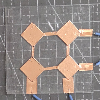
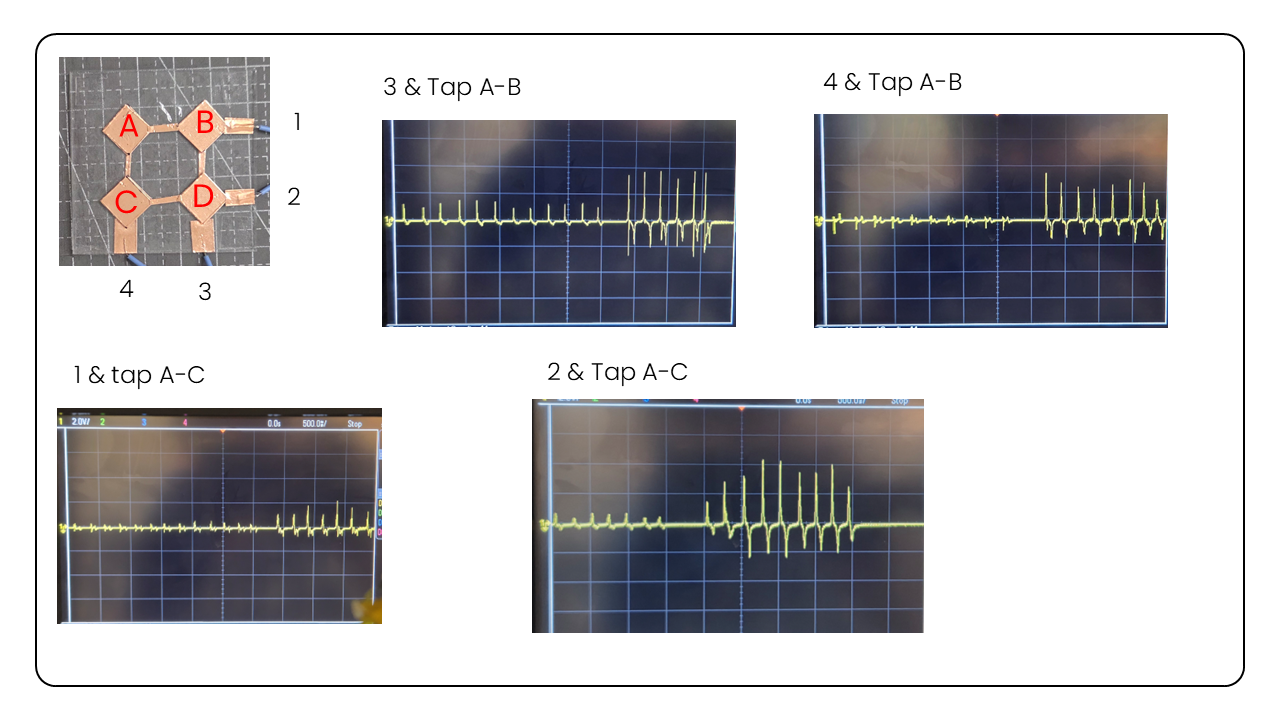
However, the 5-layer structure would be nearly impossible to successfully print using a regular 3D printer, let alone the one present in the lab (Prusa MK3 i3 — purchased circa 2019).
Thus, we decided to pivot to a different yet somewhat similar idea that would build on the successes and failures of this one — to be discussed in the next progress report.
References
Peng, C., Marzocca, P., & Tran, P. (2022). Triply periodic minimal surfaces based honeycomb structures with tuneable mechanical responses. Virtual and Physical Prototyping, 18(1). https://doi.org/10.1080/17452759.2022.2125879